 Home page Home page
 Sitemap Sitemap
|
|
|
I-40 V |
HomeProductsPRODUCT DEVELOPMENTContact |
Mechanical harvester
M-60 EV
M-50 EV
M-40 V
M-30
I-40 V
I-80 V
M-30 SP
Production millers
Bevel gear »
Ridger »
Aileron Accessory »
Milled peat harrow KÄ-18 »
Milled peat harrow KÄ-9 »
Reduction gearbox »
Reduction gear »
Combination trailers YPV-50 »
 FI FI
SE
|
Milled peat stockpiling harvester I-40 V
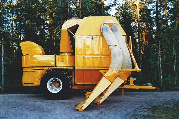
Pneumatic milled peat stockpiling harvester collects peat straight from the surface of the field.
The wagon is unloaded from the bottom and the wagon compacts the peat into stockpiles. Bottom unloading is a patented method. The blower's drivetrain is equipped with a hydraulic clutch (no V-belts). The suction duct is equipped with flexible joints to prevent damage from vibration. Nozzle is lifted up and any blockages that remained in the nozzle during loading fall out. Illuminated screen - full load indicator.
Technical data
| Working width |
4,000 mm |
| Driving speed |
6-10 km/h |
| Power requirement |
min. 80 kW |
| |
|
| Power |
120-200 m3/h |
| Blower's drivetrain |
mechanical |
| Power takeout |
1,000 rpm |
| Weight |
6,500 kg |
| Tyres |
width 774 mm, height 1,850 mm, 4 pcs |
| Height of tyres |
1,850 mm |
| Chassis |
tractive, drivetrain, mechanical |
| |
|
| Wide axle |
Distance between tyre flanges 2,800 mm |
| Peat load |
36 m3 |
| Tank capacity |
40 m3 |
| Tank width |
4,000 mm |
| Tank length |
3,100 mm |
| Total width |
7,800 mm |
| Total length |
9,000 mm |
| Total height |
5,250 mm |
| Outer width of tyre sets |
4,850 mm |
| Diameter of blower's air inlet |
1,120 mm |
| Nozzle's air inlet |
80 x 2000 mm, 2 pcs |
| Air speed in air inlet |
50 m/s |
| Blower's revolution count |
1,216 rpm |
| Amount of air |
19.9 m3/s |
| Blower's power requirement |
63 kW |
| Surface treatment |
sand blasting, priming and topcoating |
| Air and material controls (polythene plates) on the ceiling. |
    
Special features of pneumatic harvester 1-40 V
-
Bottom unloading
Loads can be unloaded onto the stockpile while driving, which grows the stockpile without a separate stockpiling machine. The stockpile becomes tight, the storing of peat improves and there is no danger of self-combustion.
- Nozzles
Looking from behind, the nozzles are on the right side of the wagon so that it is easier for the driver to monitor their operation. Looking from behind, the tractor's hydraulic control devices are on the right side of the cabin. As the driver's right hand is on the control lever, he is already partially turned toward monitoring the nozzles. As such, the driver experiences increased comfort during driving. Nozzle damage is minimised with the use of suspension and lifting equipment. Nozzles are lifted so that the air inlet points downward. Any blockages that remain during loading fall out on their own.
- Tank and suction ducts
Special attention and care has been taken with the sealing of the tank and the suction ducts. This way, the blowers' dissipation rates have been eliminated. Leaking seals on tanks is one reason why dust flows freely in the blower.
- Sheet metal parts
The sheet metal on the tank and the cyclone has been rigidly deep-textured to prevent heat-related bending caused by welding and bending caused by vacuums. This also gives the wagon a finished look. All parts have been sand blasted as well as primed and top-coated.
- Blower's drivetrain
The drivetrain is equipped with a hydraulic clutch (no V-belts).
 Print Print
|
|
Raiselift Oy - Raivalantie 524 - 39920 SUOMIJÄRVI - Finland - Tel +358 (0)45 154 9772, (0)400 126 332, (0)2 544 4141
|


